
Anchoring is one of the great joys of boating. You can get away from the crowds and expense of marinas, listen to the birds in some lovely little creek tucked away somewhere and watch the sun go down.

At anchor on the Swale
The trouble is, often enough in this green and pleasant land in anything but the height of summer, as soon as the sun does goes down, the temperature drops through the floor and you start trying to devise new and exciting methods of keeping warm. There are only so many coats, blankets and sleeping bags you can comfortably cover yourself with and still be effective at scrabble/pass the pigs. As the temperature marches lower you desperately light the oil lamp, make yet another cup of tea, boil a pot of water and put some candles on to burn. All of these create carbon monoxide in the cabin, create plenty of condensation and are pretty ineffective to boot.
After weighing up all of these factors, I decided I needed a sensible method of warming the boat to extend our cruising season.
My primary goal was having something safe. My father had a Taylors Steel Diesel Heater on his 1930’s gaff cutter Wanda, and whilst it kicked out plenty of heat and was a thing of beauty, it would invariably fill the cabin with thick, sooty smoke when it wasn’t drawing quite right (and that was a science in itself).

Taylors diesel heater
Additionally, it got (as you might expect) red hot. After a tiring few hundred miles across the Firth of Forth and up the Murray firth to Inverness, on returning to the cabin once moored up, I accidentally grabbed onto the heater – the pain of which I have not since had!
My budget was, as usual with a young family and the ships dog to maintain, as little as possible, and this ruled out the likes of Eberspecher. I looked at things like gas camping heaters, and then quickly recoiled from these when I realised they were unvented, and burning these in the closed confines of the saloon was a good way to gas my family with CO.
I started eyeing up the Propex gas heater offering which did have an exhaust. It seemed far simpler to my mind to burn gas to heat, none of that fiddly diesel compression trickery, and thus less to go wrong. Also, for a full marine fitting kit, it came in at around £500, so cheap as chips in comparison. I ordered the kit direct from Propex at a slight premium to ensure a smooth route to get support (and they were most helpful indeed). So, to fit the heater!
1.0 Plan your install
First of all, safety needs to be considered. Burning gas, or most things you might use to heat your boat, create CO (Carbon Monoxide) which is odourless and deadly, so a detector is a must. The second, more obvious point, is that gas is explosive, so getting gas to the Propex unit must be done in a robust way using copper pipe and either done by a gas safe engineer or at the very least signed off by one.
1.1 Inspect the contents of the box
When you receive your package you will note that it is very light indeed.

Ships mate carrying the booty
When you open the box you will be slightly bamboozled by the sheer array of items you will be fitting in the install process. Don’t fret too much, there really isn’t that much to it.
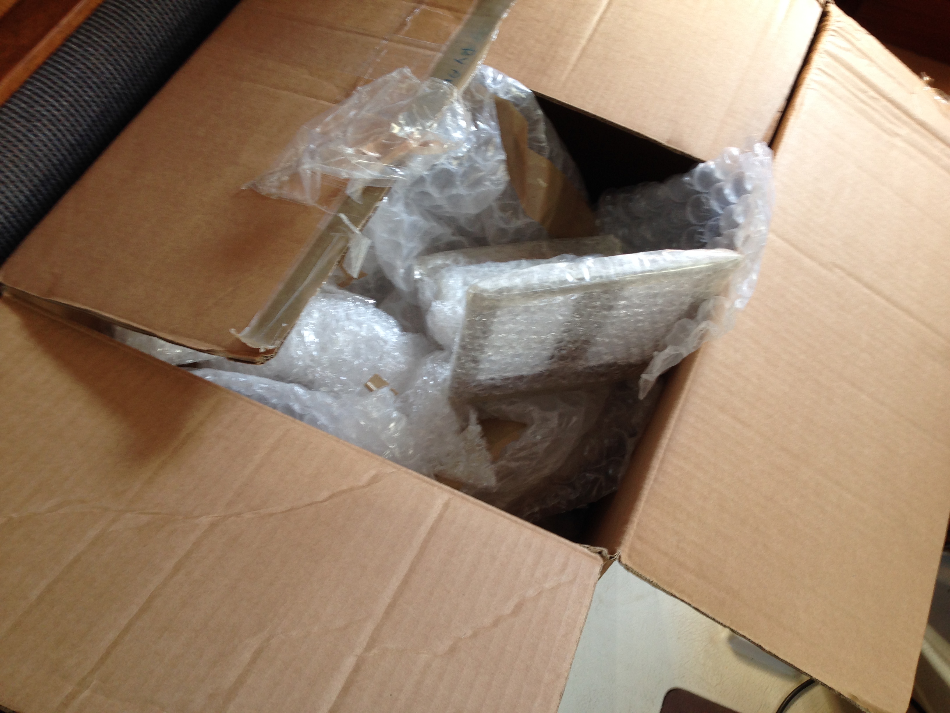
Unpacking the box
1.2 Figure out where all the ‘bits’ will go
On Triola there was no way I was going to be able to run air ducting forward on the starboard side where the gas locker was as the galley got in the way, so that meant siting the Propex on the port side. I didn’t want to take up any locker or cupboard space so resolved to put it under the deck, this would give a good route forward for the hot air ducting and a clear run aft to put the exhaust out the transom.
I had extensive help (by the end of the process circa sixty emails had gone back and forth!) from Richard Kitchener of Propex Leisure who answered my many, many questions.
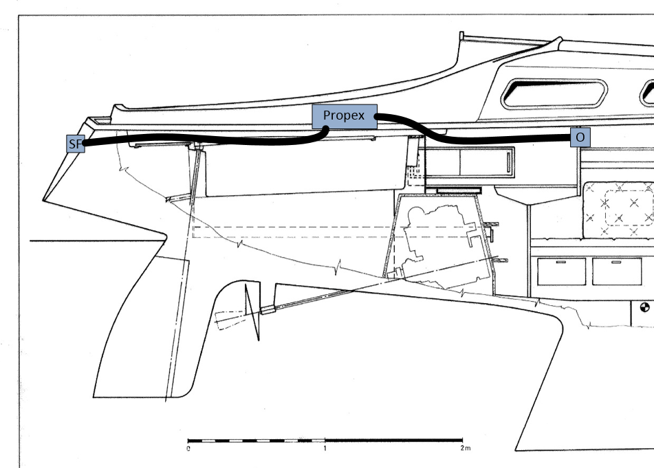
He informed me that the maximum length the combustion pipe (that’s the pipe that runs to the exhaust skin fitting) can be is two meters (the kit you get only has a length of one and a half meters, I had to order additional pipe) . The maximum length of ducting to the first outlet is one and a half meters, assuming there are no sharp bends. This somewhat limits your install options! I settled for the plan below that left the only complication being getting the gas from starboard all the way over to port.
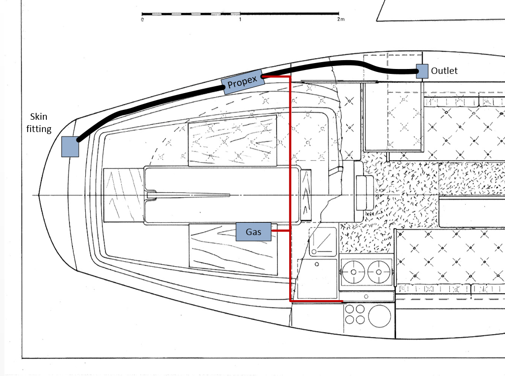
Propex install plan
2.0 Install the Propex heater
In order to attach the Propex heater to the deck, I used my trusty WEST SYSTEM epoxy to bond a wooden shim in place to mount the unit.
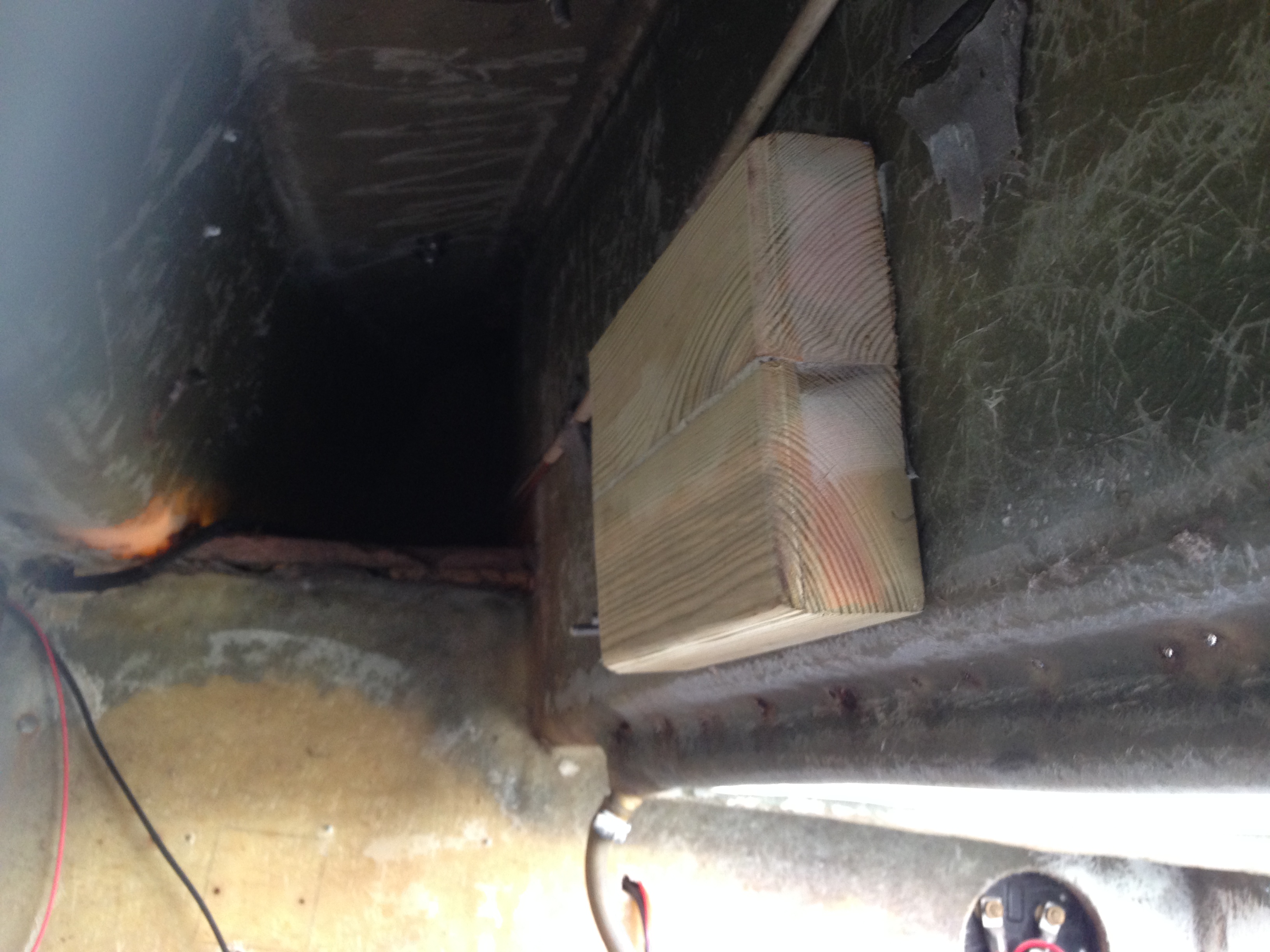
Wooden shim epoxied in place
I then added a thick layer of glassfibre over the top of the shim to firm it up, waterproof it, and make it a suitable base for the Propex heaters mounting bracket.
The heater can be orientated any way other than nose up or nose down on its end (the long edge being on the vertical) as it will put the weight of the motor armature on the bearings reducing its life expectancy. The below shows how the exhausts slot through the mounting bracket that comes with the marine kit.

Propex mounting bracket
I chose to mount the unit with the exhausts facing down with the top of the bracket you can see in the above photo mated to my new shim with six self tappers (Ignore the copper gas pipe in the below, this photo was taken at a later stage in my fit out process).

Propex heater sited
2.1 Drill two holes in your pride and joy!
It is always very hard and counter intuitive to make two stonking great holes in your beloved vessel. Armed with the skin fitting template, a hole saw and a steeled will, I set to work installing the exhaust. I was lucky enough that the exhaust run at two meters was just long enough to make it to the transom (its important to have a bit of a ‘swans neck’ on the exhaust to stop water travelling up it to the unit, so make allowance for this in your calculations). Others have reported that if they exhausted out of the hull on either port or starboard sides they could sometimes catch a wiff from the heaters exhaust.
I gaffa taped the template for the skin fitting onto the transom and dangled precariously over the aft of Triola with the drill in hand – make sure you take a look from off the boat at the alignment of the exhaust – the last thing you want at the end of this process is a wonky skin fitting. Once I was sure it was straight and true, with a heavy heart, I started the process by drilling a tiny pilot hole in the centre of the main cut outs

Drilling the transom
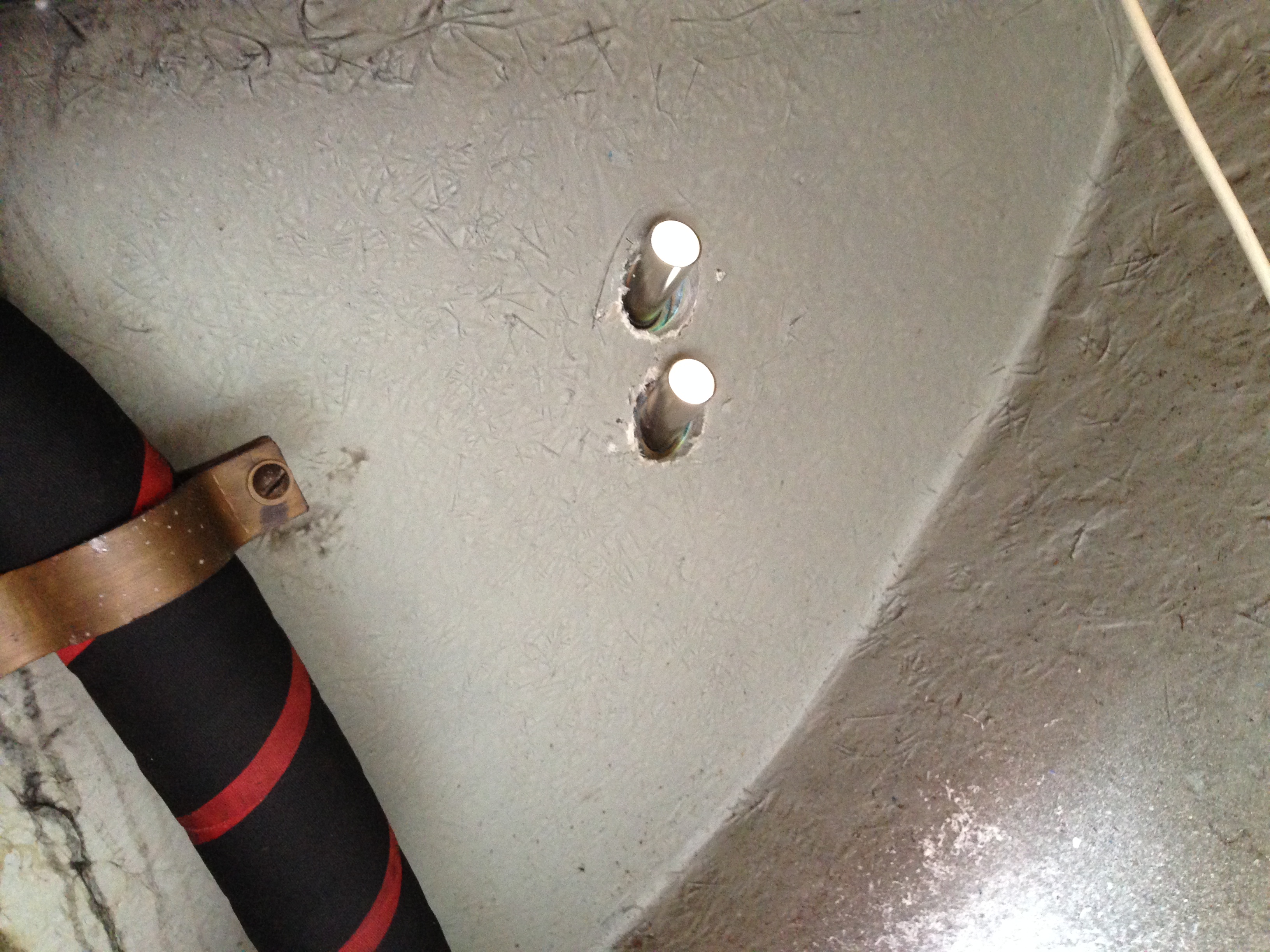
Skin fitting holes from the inside
One thing, when I drilled the holes for the first time, that I didn’t take into consideration was the thickness of Triolas hull. At around 2cm thick all around, the angle that the hole saw cut was made at was critical, meaning that when I first offered up the skin fitting to the hull, the internal hose fittings would not pass through the hull. On the third or fourth attempt, stiff but victorious, the skin fitting was in place. I bedded it down onto lots of Sikaflex, and then inserted the machine screws through my drilled holes. It helps at this stage to have a partner in crime to assist by holding the machine screws on the outside of the boat with a screwdriver whilst you do up the nuts on the inside. I had no such assistance, so had to make do with about 15 socket extensions! Once the nuts were done up, I tidied up the Sikaflex with spatulas at first to remove the majority of the excess, and then white spirit and a cloth to remove the rest – I know there is lots of advice about letting it ‘go off’ and then cutting it off, however whenever I have taken that approach it has always led to more work and more chances to take chunks out of whatever you are working on.
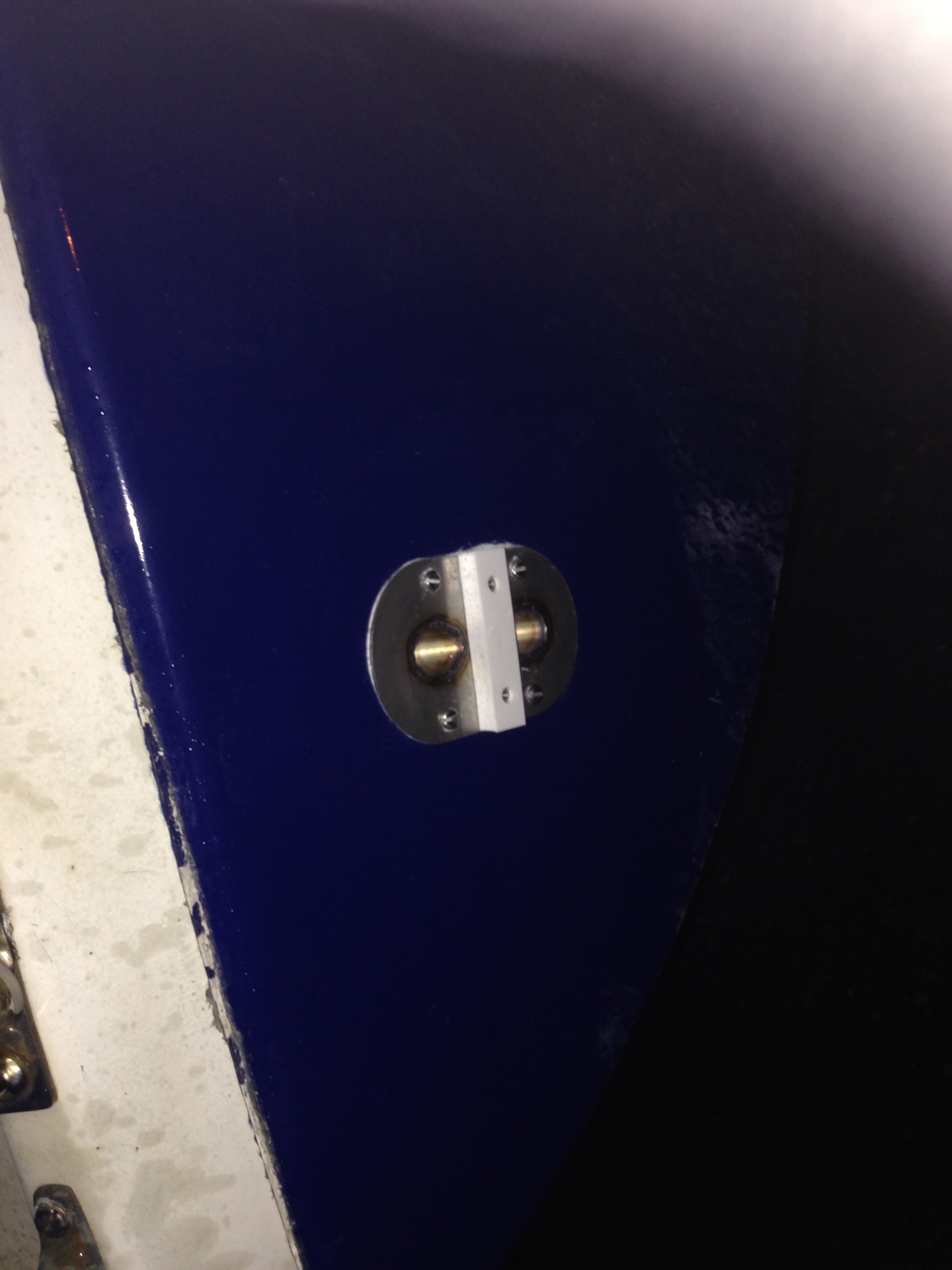
Skin fitting in place

Propex skin fitting complete
Be careful not to over tighten the screws on the final fitting of the stainless steel ‘cap’ as it will distort. Heave a sigh of relief, the most harrowing part of the heater install is complete.
2.2 Run the exhaust hoses
The skin fitting attaches to two hoses that run to the Propex heater, one of these is the flue (which comes with some heat shielding as it will get very hot when the heater is in operation) and one of these is the air intake. Make sure the flue run doesn’t come into contact with anything flammable and make sure all of these hoses are sealed with either gas jointing compound or silicon as the flue is the all important pipe that will carry the carbon monoxide away from your crew.

Flue and air intake with jointing compound
The swans neck on Triola to the skin fitting was a long steady run down to the skin fitting to vent any condensation and to make sure no sea water made its way up to the unit.
Swan neck
2.3 Run the hot air ducting
There are two holes in the end of the Propex, one is the hot air outlet and one is the recirculation inlet vent – this vent takes air from the heated space and recirculates it to increase efficiency. Within the instructions it states: “NOTE: There is no reducing spigot provided for the air inlet vent, as it is not necessary to put ducting on it.”, for our purposes we can ignore this advice (unless we are mounting the Propex unit in the cabin somewhere) as we should draw air back from the heated cabin into the unit. Both of these hot air pipe runs will need lagging in some form to prevent us from heating a cold locker rather than the boats cabin. The ever helpful and cheerful Richard suggested it needn’t be anything expensive and some rockwool ducting insulation from ebay would do the job nicely.
As alluded to earlier, the first hot air outlet must be within 1.5 meters of the unit, assuming no sharp bends, if you have opted for more than one outlet, the second outlet can be as far away as you like. This leaves you in the awkward position where the heating unit must be no more than 1.5 meters from your saloon, and no further than 2 meters away from the skin fitting exhaust. When mounting the exhaust skin fitting in the transom, this only just worked with Triola, if the cockpit were any longer, I would have had to run the exhaust over the port or starboard side.
I had purchased the two outlet kit which comes with a Y piece to split out your ducting to the second outlet, I didn’t end up using it though as I found it too problematic running the ducting to the forecabin – for a 30 foot boat I have also heard a single outlet system is ample to warm the whole space.
Ideally, the outlet should be as low as possible in the boat, however practically on Triola, the outlet ended up some way higher. Whilst not quite so harrowing as drilling holes in your boat, using the 95mm hole saw to burrow your way through bulkheads is still pretty alarming as you make your way forward from the Propex unit!
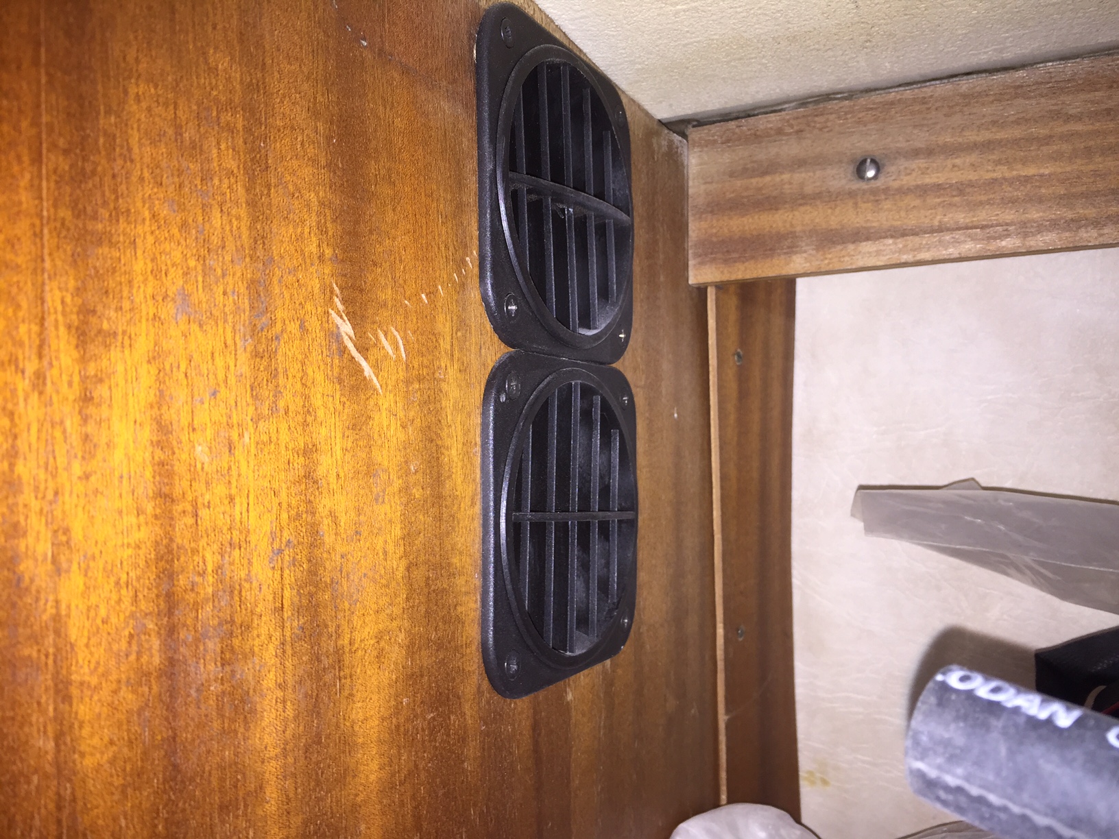
Hot air outlet and recirc inlet inside boat
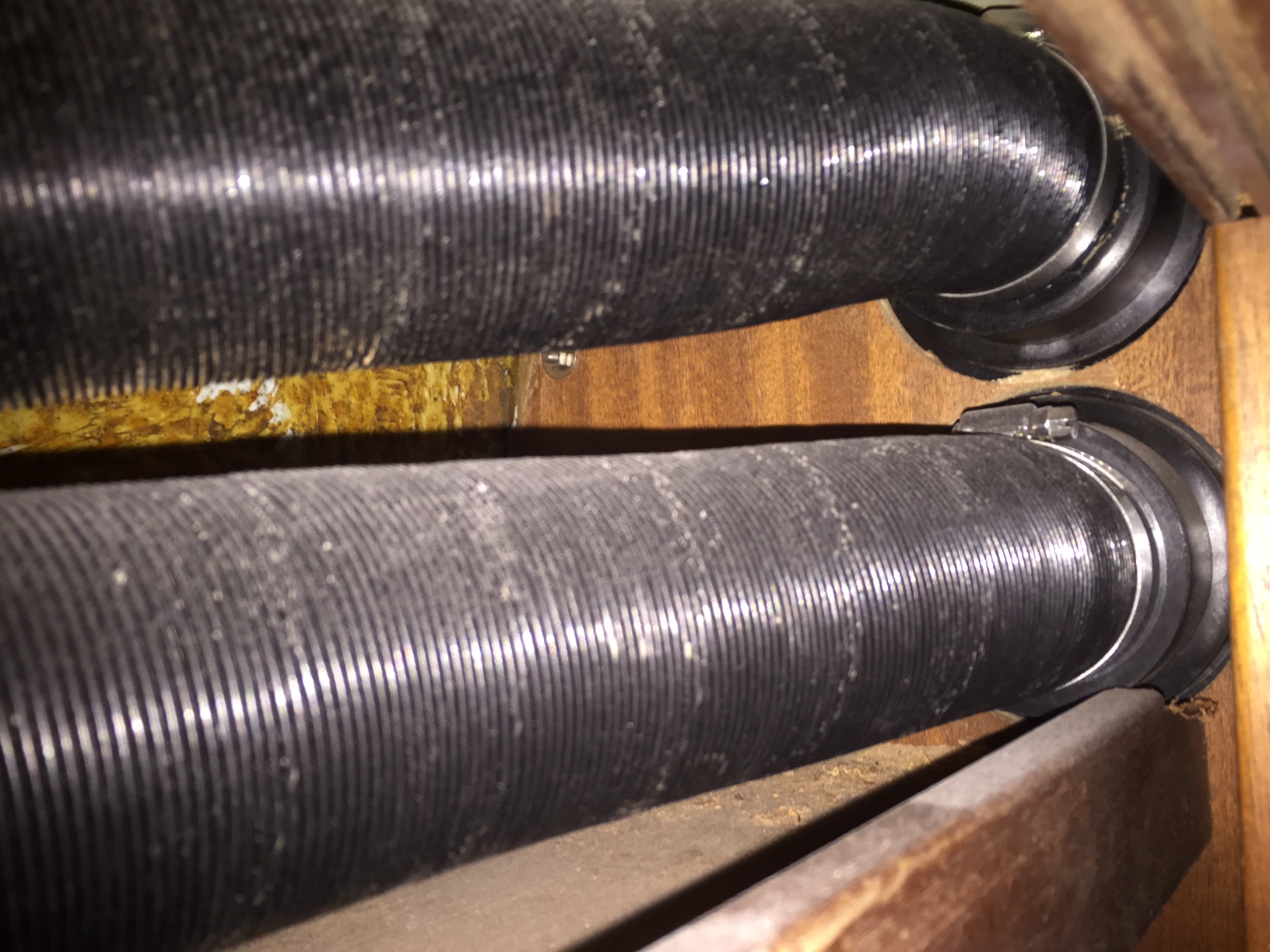
Ducting run!
On the ever useful Practical Boat Owners reader forums, David from East Coast Marine Heating & Electronics suggested that the Recirc inlet location was quite probably in the worse possible place, as the Propex unit would draw heated air back in which would affect its ability to warm the space. He also suggested the inside ducting runs be lagged too to stop heat seeping out into the lockers and not warming the space.
2.4 Do the wiring
There are two looms that come with the heater – one to power the unit, and one to provide control from the thermostat.
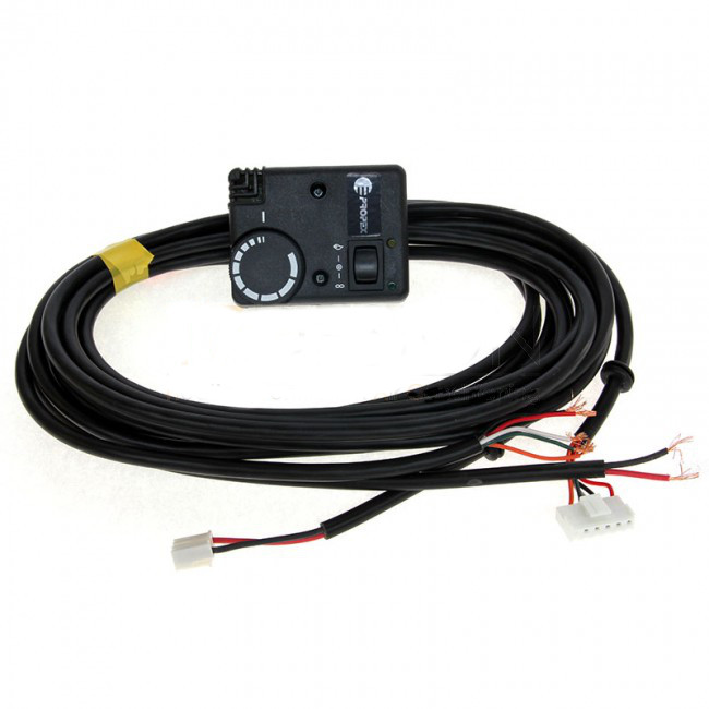
Propex HS2000 wiring looms
The ends of the looms with plugs on connect directly to the Propex unit – the only way to attach these in reality is by unmounting the heater, undoing the two torque screws holding the side cover on, and then attaching the plugs as below. Each wire has a rubber grommet that slides over the holes in the case by the air outlet.
Wiring up the Propex unit
Drill a hole in the bulkhead you are looking to mount the controls and then wire them up as below before fixing on the case to the controls.

Propex control wires installed
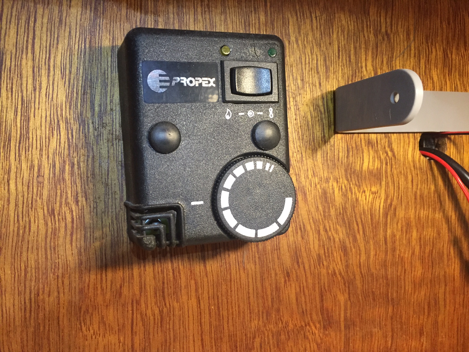
Caps over screws and dial attached
The final step is to run the red power cable back to your breaker or, as in my case, fuse box via a toggle switch, and the black to your negative bus bar, and your electronic install is complete!
3.0 Install the gas!
This is no mean feat, and the most complex and potentially dangerous part of the operation. See my article on fitting out your gas or get a professional to complete this part for you!
4.0 First firing up…
With everything set up, gas turned on and 12Vs flowing to the unit, the moment of truth has arrived. I found the instructions at this point a little vexing. Effectively the process is:
- Turn the dial fully anticlockwise.
- Press the switch to the LEFT – Effectively this means “Heater on”. The system will do a 15 second purge to get air out of the system and draw gas through. At this point I had an error and put my head in my hands – something was wrong and the light was flashing twice, pausing, and then flashing twice again! Reading the instructions, it suggested turning the unit off (setting the toggle switch ‘flat’), leaving it for around three seconds, and then trying to start it again. On the third attempt the heater fired!
- To turn off, set the switch to the ‘flat’ position (the position in the photo above). The unit will run the fan for a further three minutes as it cools down and purges.
I was impressed by the heat given out and the fact I could barely hear anything running at all. Another job completed!